© 2020 - 2021 Keen Electronics Limited
e-mail: sales@keenelectronics.co.uk Telephone: 07500 24 11 33
127, New Road, Bromham, Chippenham, Wiltshire, SN15 2JA
Company Registration No: 2613501 VAT Registration No 596069885

Keen Electronics Limited


<< Back to Product
INSTALLATION INSTRUCTIONS
INTRODUCTION
The 2000 CONCEPT KEL motor home alarm is straightforward to install, BUT PLEASE TAKE A COUPLE OF MINUTES TO READ THESE INSTRUCTIONS !
The alarm system consists of the following components :-
- Control box - with flying lead and terminal block that can be un-plugged after installation for testing/fault finding. This can be mounted in any convenient location in the motor home, in a bed box with the charger is often most convenient.
- Waterproof siren - that can be mounted anywhere - behind a ‘fridge grill or over grille in the floor. Position the siren so the sound can be heard outside the vehicle.
- Key Fob/s - carried by the user
- 1 or 2 PIR head/s - that should be fitted at eye level "looking down" the living quarter’s interior. Avoid fitting where it "looks" straight at a window.
- Door Switch - that should be fitted to the living quarter’s door, on the hinge side.
INSTALLATION
Ensure that the 12 Volt leisure battery is disconnected and the mains hook up is disconnected.
It’s well worth spending a few minutes deciding where to fit the alarm system’s components. Often wiring can be run at the back of bed boxes and cupboards, which saves drilling through the floor and working underneath the vehicle. The wiring diagram shows how the system is connected.
Control box
Once it’s location has been decided screw the small white mounting plate to the floor or a suitable panel. The control box then fits onto the mounting plate and is slid down until it "clicks" into the locked position. To remove the control box simply slide the case upwards until it is released from the mounting plate. Screw the terminal block to the floor/panel.
Siren
Remove the mounting bracket fixing screws, then screw the mounting bracket in the desired position. Re-fit the siren body into it’s mounting bracket and re-fit the fixing screws, ensure these are reasonably tight. Use the 2 way terminal block to connect the siren wires to the wires going to the control box. Fix the terminal block to the motor home with a single screw.
PIR Head/s
These should be mounted at eye level "looking down" the living quarters, usual mounting positions are at the front, on either side or in the centre. Avoid mounting a PIR head where it is directly facing a window. Carefully remove the front half of the case by undoing the single screw, then carefully hinging the front half upwards. The PIR head should be mounted using the screws supplied. Connect the three wires from the control box as shown on the wiring diagram. Refit the front half of the case and fix it in place with the single fixing screw. - REFER TO THE SEPARATE SHEET ON THE PIR FOR MORE INFORMATION.
Door Switch
This should be fitted to the hinge side of the main door into the living quarters. Drill a suitable size hole in the door frame for the switch and in the door edge for the magnet.
ELECTRICAL CONNECTIONS
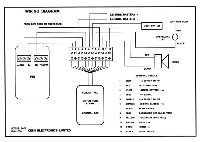
Please refer to the wiring diagram.
Connect the door switch to the control box using twin flat loudspeaker cable, polarity is not important.
Connect the siren to the control box using twin flat loudspeaker cable, observe correct polarity - red siren wire to siren + and black siren wire to siren -.
Connect the PIR head/s to the control box using 3 core cable as shown in the wiring diagram.
Locate a convenient point in the wiring to connect to the BRAKE wire - live feed to brake lights.
Finally, connect the 12 Volt supply from the leisure battery to the control box. Do not use twin flat speaker cable as it is rather thin for this application. A 0.75mm or 1.0mm cable (24/0.2) or similar is recommended. In some motor homes it is practical to connect these wires to the battery charger, but in others it may be easier to connect direct to the leisure battery (always through a 1 or 2 Ampere in line fuse)
The alarm installation is now complete and ready for testing, ensure that the key switch is in the anti-clockwise (OFF) position. Then re-connect the leisure battery to test the alarm.
TESTING THE ALARM
Press the "Alarm" button on the key fob to switch the alarm on, the siren should "cheep" twice then remain silent. Press the "Alarm" button a second time to switch the alarm off, the siren should "cheep" once. When the alarm is triggered the siren should sound for 2 minutes, unless switched off with the key fob. IMPORTANT NOTE - THE BUTTON MUST BE PRESSED FOR A COUPLE OF SECONDS
Opening the main door will trigger the alarm instantly (no entry delay time) then the siren will sound for 2 minutes.
Moving inside the living quarters will trigger the alarm instantly causing the siren to sound for 2 minutes.
Operation of the foot brake will trigger the alarm instantly causing the siren to sound for 2 minutes.
The control box has three (one PIR model) or four (two PIR model) LEDs on it’s lid. Once an alarm has occurred the relevant LED will light and will remain lit until reset by turning the control box off using the key switch. This facility is useful for fault finding and test purposes.
Switching the alarm off with the key fob will not reset the LEDs.
WIRING DIAGRAM